31 Aralık 2010 Cuma

PIC Controlled Alarm Clock

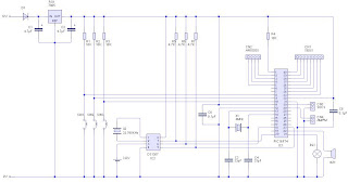
Hier ist ein Wecker-Schaltung, die auf der Grundlage von PIC gesteuert. Zwei Platinen zusammen eine einfache PIC basierte Design bestehend aus zwei miteinander verbundenen Vero-Board-Karten. Die größere der beiden Leiterplatten enthält die 5V-Leistungsregler, die Display-Prozessor (ein PIC-16F74), den Echtzeit-Taktgeber (Dallas DS1307), backup Batterie 3V und Summer. Finden Sie unter das Schaltbild unten für Details.


Das PIC-Board sah aus wie dies vor Einbau der ICs und LED/Switch Draht-Verbindungen. Es fehlt auch die 1 Hz Signal-, I2C-Uhr und I2C-Datenverbindungen zwischen den PIC und RTC-Chips. Ich habe einen 4 MHz Resonator mit Load-Kondensatoren statt des Kristalls und separate Kondensatoren gezeigt auf dem Schaltplan gebaut. Auch ich eine weitere Link Draht hinzugefügt, nach der Einnahme dieses Foto zum GND - Ve-Terminal von der backup-Batterie herstellen.(Das Kupfer verfolgt führen Links-nach-rechts auf diesem Board mit Schnitten zwischen den IC-Pins und in ein paar anderen strategisch wichtigen Orten.


Der PIC-Mikrocontroller ist so programmiert, dass die Echtzeituhr mit I2C seriellen Kommunikation mehrmals eine zweite lesen und Aktualisieren der Anzeige.Es ist keine Zeit zu halten selbst. Sogar das pulsierende zentrale paar LEDs sind angetrieben von den Echtzeit-Taktgeber (über ein Ausgangssignal 1 Hz) und der von der PIC gelesen wird.

Der PIC führt zwei andere Funktionen;Es vergleicht die Zeit gegen die Alarm-Einstellungen, um zu bestimmen, wann es gehen sollten und auch Handles Zeit, Datum und Alarm einstellen. Die 16F74 hat keine EEPROM von seinen selbst, so dass alle Einstellungen in der DS1307 gespeichert sind und lesen auf Power-on-Reset durch. Ich hatte geplant, mount Connectors auf dem Board für alle den Switch und Drähte angezeigt, aber am Ende gab es nicht genügend Platz, damit ich die Drähte direkt eingelötet

Ich bestellte ein 16F74 Mikrocontroller von Farnell, weil es mehr als genug i/O-Pins und I2C auf Chip unterstützt.Nachdem ich den Chip erhielt und das Kleingedruckte im Datenblatt entdeckte ich, dass das SSP-Modul nur wirklich geeignet für einen I2C Slave war. Wirklich, was ich brauchte, war ein MSSP-Modul. So mein Code deaktiviert das SSP-Modul und erzeugt die I2C master Clock und Data Signale (auf die RC3/SCL und RC4/SDA Pins) mit einem 'Bit-knallte'-Ansatz.

Eine kleinere Platine enthält alle die Anzeige LEDs und sitzt oben die base-Board auf Kunststoff Abstandsbolzen.


Die folgende ZIP enthält alle der PIC-Assembler zu müssen, um den Wecker zu programmieren.Der Code ist in zwei Teile: ein Projekt baut eine Bibliothek von PIC-Routinen (einschließlich Start Power Module) und anderen enthält den Uhr-spezifischen Code.Erstellen Sie zuerst die Bibliothek.

Quelle Code ZIP (30,6 KB)

Quelle: PIC Controlled Wecker

Sehen Sie mehr: CdS Fotozelle Detector


24 Aralık 2010 Cuma

Smoke alarm detectors

Is a simple fire alarm circuit based on detection of fire LDR and lamp of a few. Uses a very simple detect smoke in the air approach. Works produced by the smoke during fire.The remote sensing circuit alarm produces an audible alarm if fire exits with smoke.

This is not an ideal approach probably because the brightness of false alarms, the cause intéressante.Juste atmosphere but experience includes all the lights, in the experimentieren.Und please count on you as a substitute for a real alarm fire - device.


If there is smoke-free on LDR LDR.The resistance bulb low fall and ECA therein (see lamp) .the therefore transistors and nothing makes geschieht.Wenn thing enough smoke, light falling on LDR to conceal the RDA increases resistance and do voltage through it.Now transistor is to be moved ON.This empowered the IC1 and will strengthen gives 5V.This powers of IC (IC2) to play music by Music.this UM66 generator by IC3 (TDA 2002) drive speakers.

D1 and D2 diode in combination fall 1.4 V nominal voltage (Fujifilm) UM66 .um 66 type can support more than 4V.

Customize note:
  • The speaker can be a speaker for acute 8th.
  • R4 POT can be used to adjust the sensitivity of the alarm.
  • TOPS R3 can be used for a different from the alarm volume.
  • (General purpose NPN transistor BC548 BC148, 2N222) can be used for the first quarter.
  • The circuit can be provided on a 9 v battery or a DC power supply 9.
  • To enjoy a brilliant with a resistance of 1 k series to use LED bulb.

Source: smoke alarm detectors

More information: CdS photocell sensor


18 Aralık 2010 Cumartesi

Help for the car parking sensor

This sensor circuit, p arking the car near the garage wall designed for security. D7 LED illuminates if bumper wall distance 20 cm. D7 + D6 illuminate approximately 10 cm and D7 D6 + D5 6 cm. In this way, you will be notified If approaches too close to the wall.


All distances between sensor can vary mentioned in this procedure, depending on the infrared emission and receive used organizations and are affected by the color of the surface significantly réfléchissante.Réduire Empfindlichkeit.Offensichtlich black device surfaces, can this circuit in other applications such as the level detection for liquids, proximity, etc devices.

Source: parking sensor support

More information: photoelectric detector


11 Aralık 2010 Cumartesi

Simple Metal Detector

Es ist ein einfaches Metall-Detektor-Design, die die sehr guten Eigenschaften hat. Das Prinzip der Operation, die eine von den klassischen Systemen unterscheidet (BFO, senden-empfangen-bekannt als die "zwei-Boxen" Metall-Detektor, induktive).


Im dynamischen Modus wird verwendet, um die Ziele in Einmischung Umgebung zu finden. Es ist von der Theorie der Signal-Filtration bekannt, dass wir optimale Filter - die besten ein für das Extrahieren von das Signal mit maximale Signal/Rausch-Verhältnis konstruieren kann, wenn Signalverlauf bestimmt wird. Dieser Filter wird als optimale übereinstimmenden Filter bezeichnet. In unser Gerät haben wir digitalen optimalen übereinstimmenden Filter als Teil der Mikrocontroller-Software realisiert.Der Filterparameter sind optimiert für effektive Ferro- und Nonferro-Ziele-Erkennung auf 0,5-1,0 m/s Geschwindigkeit des Sensors.

Features von der Metalldetektor:
Stromversorgung............................. 4. 5-6V;
DC Verbrauch zur..15 mA;
Angabe.................................. .sound + 8 LEDs;
Modi....................................... .static oder dynamische;
Discrimination.............................Ferro/Non-Ferro.


Metal Detector SCM, Layout und PCB


Schalter gesteuert (v1 und v2. 0 des Firmware-Versionen):
S0: Reset Gerät;
S1: reserviert;
S2: auf - Schwellenwert Hight, off - Schwellenwert niedrig;
S3: Messung Zeit auf - 30ms, off - 120ms;
S4: Autooptimierung on / off (im dynamischen Modus nur);
S5: Modus auf - statische, off - dynamische.


Metall-Detektor-Coil-Design

Ca. 100 locken 200 mm Durchmesser.Kupperlegierungen Draht in Isolation 0,35 mm Durchmesser


Quelle: Metalldetektor
Finden Sie mehr: Infrarot Light Foto-Detektor


4 Aralık 2010 Cumartesi

Clock radio time signal

Listen to the radio clock of signals of radio programs of correcting the time on the computer's clock and radio. Radio clock allows signals time different LF and RF R Adio stations standard frequency and time service sent to decode. Time radio to your computer for a radio station received a suitable recipient station code and compares it to the local time on the computer.

Radio clock today can the following decoding time signals.

Record radio clock you festlegen.Dieses additional functionality can enjoy it in your auto PC time radio clock register here.

Radio controlled clock
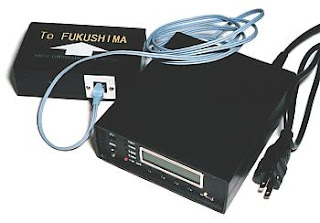
In these pages that I am a vorstellen.Aber radio controlled clock that this watch works with Japanese radio clock system, carried out for countries that do not use this device of Japan, how to organize your ist.Bitte system in your country about the content of these pages.

Remote clock and Photo Editor schema